

When databases were sized in megabytes rather than petabytes, their design was a well-defined discipline of data analysis and implementation. A progression of modeling steps – from conceptual and logical through relational and/or physical – promised successful deployment.
But as we passed more orders of magnitude in data volume, we seemed to stop seeking modeling approaches to manage that volume. So the question arises: Is logical data modeling obsolete?
To arrive at a reasonable answer, we’ll have to recover some forgotten lore about data modeling.

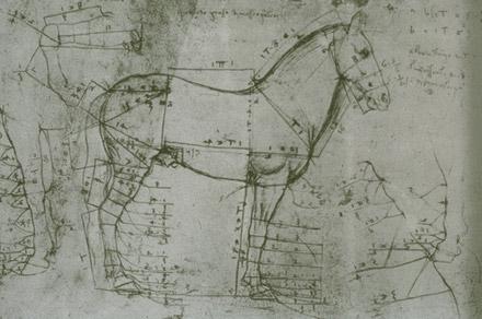
Figure 1: Two Renaissance sketches. One figurative, one very exact. Which is better?
A Funny Thing Happened on the Way to My LinkedIn Group
In January 2016, Abhilash Gandhi asked a question on the LinkedIn Data Modeling and Meta Data Management group: “Is logical data modeling obsolete?” What followed was a tremendous thread that brought out a lot of perspectives, information, and opinions. With careful reading, I found that while most interlocutors agreed that logical data modeling is important, they held many different concepts of what it really is.
The TL/DR is this: No. Logical data modeling is not obsolete.
But what does that mean?
So What Is Logical Data Modeling?
Logical data modeling is really a placeholder in a notional sequence of modeling, implementing, and deploying a relational database application. It assumes a software (database) development lifecycle. Let’s explore different views of this lifecycle and of the logical phase. When we’re done, we’ll have defined logical data modeling and explained why it’s still important.
Phases of Database Project Implementation
In the common usage established by ANSI in 1975, data modeling goes from abstract to concrete in three steps. This preceded the popularization of the relational data model. (Despite the fact that it was proposed in the 1970s, the relational model was little used until the 1980s.) These modeling steps are still embedded in many relational database projects.
There are several variations in the ANSI theme. The most common phases are as follows:
- Conceptual
- Logical
- Relational
- Physical
If we want to understand various kinds of modeling, let’s first have a look at the associated jargon.
Entities, Attributes, and Their Friends
We start with a value. This may be a number, a date, or a chunk of text. Domain refers to the meaning for a value or a set of possible values. When we have a value with a consistently and widely used set of units, value domains, or applications, we call this value a data element. A data element may be a ticket number, a temperature reading, a hair color. (Some modeling approaches omit the notion of data elements or domains.)
Domains establish sets of values for data elements.
In all the techniques and stages of data modeling, the concepts of entity and attribute are universal. An entity is the “thing” that must be manipulated as a data object. Entity represents an indivisible concept that consists of data elements. Each data element in the entity is called an attribute. Conversely, we could say that we build an entity by attributing data elements to it. You create an entity as a whole, and you delete it as a whole.
Each entity collects a meaningful and logically-indivisible group of data elements, each with a distinct role.
One key disagreement about entities is ownership. What does it mean for an entity to be owned by another entity? Two things are typically connoted by ownership, such as when A owns B: first, that any modifications of B are mediated, allowed, or disallowed based on the properties of A. The second is that B’s lifecycle is dependent on A; specifically, deleting A causes deletion of B. You may refine your take on this. Can an entity be created or deleted based completely on its owning entity? I don’t want to take sides here, but it is important that you consistently apply your definition of ownership throughout your model and your database.
Ownership takes us to the last of the jargon: the notion of relationships. Anything that correlates one entity to another is a relationship. This may be ownership or reference, and there are different cardinalities that may apply: 1-to-many (1:M), 1-to-1, many-to-many (M:N), and optional relationships.
A relationship associates two or more entities with a meaningful correlation and a relative cardinality.
Notations: If It’s a Model, Draw It!
One of the issues complicating modeling activity is the variety of notations. Logical data models are often presented in entity-relationship diagrams. Peter Pin-Shan Chen created the entity-relationship (E-R) model in 1976. He presented it with a well-defined notation that used diamond shapes to express relationships. Diamonds are terrible at containing text, so a lot of E-R diagrams have no diamonds. (Sorry, Professor Chen.)
A lot of other methods have been added since then. Here are the key ones:
Decades-long abuse of Chen’s idea of the entity-relationship model has made E-R a useless term.
| Model Name | Date | Definer | Notes | Example |
|---|---|---|---|---|
| Bachman | 1969 | Charles Bachman | First widely-used data modeling notation, which predates relational database theory. Presents entities as first-class logical data elements. |
|
| Entity-Relationship | 1976 | Peter Chen | Distinguishes relationships from entities. Diamonds are expressive but unwieldy for text. |

|
| Information Engineering | 1981 | Clive Finkelstein | Expresses the cardinality of relationships. Also known as crow’s foot notation. |

|
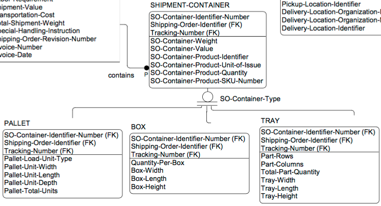
| IDEF1X | 1985 | Mary Loomis and Thomas Bruce | Provides explicit support for subclass and one-of alternative relationships. Allows explicit key and constraint representation. |
|
| Barker | 1989 | Richard Barker | Similar to IE, but adds attributes and alternative relationships. |
|
| Object-Role Modeling | 1995 | G. M. Nijssen, Terry Halpin | Emphasizes fully- specifying each data relationship from both sides. |

|
| Unified Modeling Language (UML) | 1997 | Object Management Group (Booch, Jacobsen, et al) | Focuses on object modeling rather than data modeling per se, but directly applicable to relational data modeling. |
|
I find that any diagramming notation used consistently is better than any other used inconsistently. You’re using a diagram to communicate. Make your diagrammatic language clear and consistent. And never assume that the users know any particular notation. There is no common language for data modeling any more.
Provide complete and precise definitions and illustrations for any diagramming notation you use.
Conceptual Data Modeling
Conceptual data modeling is accomplished primarily by identifying the entities. Typically this starts as listing the main “things” in the business process that you are trying to automate.
Suppose you take some text describing the business process and isolate all of the nouns. How do you make sense of them now? Should any be combined? What are the relationships? What’s missing?
Typically, a vague diagram emerges in the early stages of data modeling. Only the entity names are shown, with some connecting arcs illustrating a relationship. The modeler need not tightly restrict the definition or numbers of “things” in the model, because that could exclude something important. It is only after repeated iterations of the questions of redundancy, relationships, and gaps that the conceptual data model is formalized; the “things” become entities that exhibit the requisite indivisibility and independence.
Conceptual data modeling enumerates possible data entities in an application or system.
Logical Data Modeling
Logical data modeling doesn’t necessarily have a clear starting point. Progressive refinement continues once the basic entities have been specified. Often, that list of entities will keep changing during logical data modeling.
The primary activity of logical data modeling is specifying relationships among data entities. The secondary activity is elaborating the attributes in each data entity. Practically, though, adding the attributes is often what enables the final definition of entities.
Normalization
The principal practice of defining data relationships for relational databases is normalization, specifically as developed from Edgar Codd’s original definition of the relational model. According to normalization and other modeling principles, a data model may be terrible – yet all the stored data may be completely correct. However, as data is added, modified, and deleted, the data model makes a big difference in keeping the data correct. Dr. Codd’s objective, borne of painful experience in database systems, was to systematically reduce the likelihood of data corruption. He and various successors defined progressive levels of data normalization. First, Second and Third Normal Forms (1NF, 2NF, 3NF) are the first levels; there is also BCNF (Boyce-Codd Normal Form), 4NF, 5NF, and 6NF. A database is usually considered “normalized” if it meets 3NF or BCNF rules.
Practically speaking, normalization often seems to decompose the data entities. It constantly breaks attributes out of one entity and into a different entity. Perhaps you start with John Doe’s business card as a single entity with attributes like name, address, phone, etc.
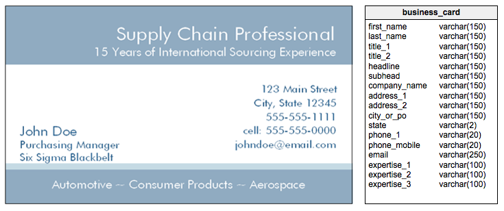
Let’s focus on the phone numbers here. How many does Mr. Doe have? Normalization would turn Mr. Doe’s card information into separate entities for person, address, phone, email, and qualification. This seems to make it harder to manage data and program applications – until you hit the eighth entity that reuses a phone or address. Then you realize you’re now saving effort and improving correctness.
Relational normalization restructures data into consistent tabular form with minimal redundancy. It is distinct from the other transformations known as normalization.
Send in the Keys
I’m about to make an intentional, and controversial, departure from the normalization approach advocated by Dr. Codd and his successors. This is in the assignment of keys, which for Dr. Codd always meant unique keys capable of individually identifying each row. The notion of keys exists in each step of normalization, but in our case we will move the specific definition of keys from the logical to the relational modeling phase.
The modeler must choose whether to use keys to inform entity definition or to dictate entity definition.
Constraining Attributes to Domains
We may think of attributes loosely, as numbers or text or dates. However, in logical modeling we need to assess and assign what those attributes really are. This has two aspects. The first aspect is the mechanics:
- How many digits in a phone number or post code?
- What are the upper and lower limits of a number?
- Should a number allow fractions?
- Does a date include the time of day?
The second aspect is in the meaning, usage, or measurement of an attribute. For example, the value “Washington” may occur in a first name, last name, city, or state. Those usages are very different. So we need to know:
- Does a number refer to a temperature or a distance?
- Does a name refer to a place, a person, etc.?
All such attribute qualities segregate them from other attributes and limit the values they can meaningfully store.
According to this perspective, an attribute’s nature constitutes its domain. As in set logic, each value for an attribute must satisfy the limits of the attribute’s domain. The values are members of the domain. Attributes are in fact constrained by the limits and restrictions of the domain. These may again occur as mechanical or semantic constraints on values. The occurrence of the same domain in multiple entities often provides a valuable expression of their relationship or of the congruence of different data entities.
Logical modeling gains precision by ascribing each attribute to a tightly-defined domain.
Understanding Relationships Between Entities
At this point, we have a bunch of entities, many of their attributes, and some idea of relationships. Let’s fill in those relationships.
The main thing characterizing a relationship is relative cardinality. A vehicle may have two, four, eight, or more wheels. The relationship of vehicle to wheel, therefore, is 1-to-many. But wait... does every wheel have a vehicle? No; spare wheels don’t have a vehicle. So the relationship is zero or one vehicles to two or more wheels.
Going back to our business card example, how about that address? Is Mr. Doe the only employee at that address? Maybe he is, but that’s pretty rare. Most people share a business address with others. What does the model say?
Looking at the model, it now seems that Mr. Doe can have two or more addresses. Oh wait – we weren’t talking about Mr. Doe listing his Bermuda office alongside his local one. We were talking about Ms. Tamarack and her 40 employees sharing the same address, not one person sharing different addresses! So we need to introduce a new table to bridge them:
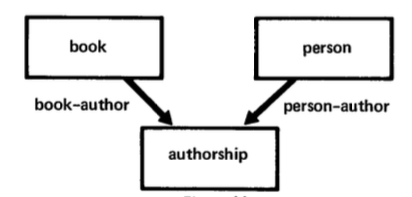
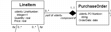
By interposing the person_address table, we have allowed addresses and persons to share each other; we’ve created a many-to-many relationship. In the Chen E-R notation, it might look like this:

Note that while I am showing a relationship between two entities, it is possible to have three or four entities in a single relationship. You don’t have to reduce all relationships to binary.
Relationships Have Names
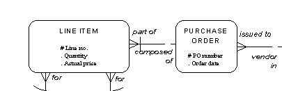
Typically, there is only one relationship between two entities. But as we’ve noted, John Doe has two phone numbers. If we have two entities called Person and Phone, we may have two different relationships between Person and Phone – one for their office phone, one for their mobile number. Some modeling notations explicitly label each relationship. We’ll try this in Chen notation again:
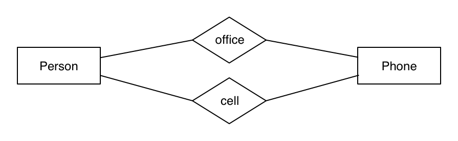
In relationships, names and entity roles are as important as relative cardinality.
Relationships May Become Entities
In our non-E-R Person-Address relationship model, instead of a diamond between Person and Address there is something that looks like a table. Is it? Or is it an entity?
In my experience, bridge relationships between entities often turn into entities themselves. How might this happen? A typical circumstance is that the relationship changes over time. For a person and an address, that might turn into Occupancy. This leads to questions like Is this a permanent residence or a vacation residence? Do we need to contact Dr. Norbert about the expiration of his lease? How long has he lived here?
We’ve endowed this relationship with a lot of information. That affects how the relationship is used, how the Person and Address information is used, and generally increases the expressiveness of the model. The relationship of Person to Address becomes a meaningful business object on its own – its own entity. The modeler should expect this.
Business Data Model
Now we’re starting to look at business decisions rather than data modeling decisions. If we are renting out apartments or offices, we might very well be interested in an Occupancy entity. If we are sending legal mail, we might only want one “legal residence” address and ditch the rest.
What are we going to do with our entities and relationships? We have a business or organization, and it has business objects, business processes, and business objectives. Whatever these happens to be, they will guide our decisions now. This is where you stop abstracting the facts you’ve found out about your data, and start applying them. Different applications and different business will mean different models for seemingly identical data.
Is That Really Logical Data Modeling?
This is not a complete business model by any means, but it depicts what I consider logical data modeling: a stable set of meaningful data entities, along with relationships that show the cardinality between related entities. The ongoing question with logical data modeling is whether relational data modeling is somehow “not logical”.
Now that we have restricted it to the definitions of entities, domains, and relationships, we have a good handle on the logical model. At this point, we can think about how to query the data entities; we can start to perform business operations and answer business questions. But we can’t install, load, or use the model yet.
Relational and Physical Modeling
The steps involved in relational and physical modeling – which are sometimes conflated – are what turns a logical model into a working database. Simply put, a relational model may be applied to any DBMS and any deployed configuration. A physical model is the blueprint for making that application.
Setting Naming Conventions
In the relational stage, having naming conventions for entities and attributes becomes a necessity. Names must make sense. Prefixes may be used to show a grouping of tables; suffixes can show the type of object. When naming conventions are consistently applied, later users can quickly make sense of the model.
Modeling Domains in a Relational Sense
The attribute domains in a logical model may have a tight or loose specification. Here, we’ll make the specification as tight as possible in relational terms. Perhaps a domain is simply a reusable set of constraints, such as “Number between 1 and 100” or “Text matches 'abc%' ”.
Others may involve more complex checks. Some will be dimensions that need to be kept segregated, perhaps to avoid storing dissimilar values – i.e. “air pressure” and “molecular mass”. Still other domains will be turned into reference tables, such as “countries” or “continents”.
Entities Become Tables (or “Relations”)
The primary and simplest aspect of relational modeling is to turn all the logical model’s entities and attributes into tables and fields. This will also apply the tight, relational-model domain definitions to the associated attributes.
Defining Keys
The design of each table’s keys, making each row unique, is the principal difference between logical and relational modeling. (At least in my opinion, although I am again deviating from orthodox Codd.)
Following Chen, I use a “logical modeling” that assumes a uniqueness of identity rather than specifying each attribute’s participation in that identity. In this approach, relational modeling designs the keys. At the relational modeling step, any table may have a unique key with some of the following qualities:
| Quality | Definition |
|---|---|
| Natural Key | A natural key is one in which the actual domain value is used as-is. An example would be a table of colors in which an RGB value is the key: the values uniquely identify the color, so they are a natural key. |
| Compound Key | In a compound key, the identity of a single row is defined by multiple attributes. In the case of shoes, you’d uniquely identify my left bunny slipper as “Andrew Wolfe” “bunny slippers” and “left”. |
| Surrogate Key | A surrogate key is one in which a meaningless value is generated to represent one or more attributes. Typically this is an incremental sequence number, but UUID (universally unique identifier) surrogate keys are becoming common. This type of key may serve as a proxy for a unitary or compound natural key. |
We humans are very much used to surrogate keys. A person is not a number, but many countries assign national identity numbers to people for insurance or employment purposes. These numbers can act like surrogate keys. Vehicle identification numbers and part numbers are also surrogate keys. Military unit numbers, typically meaningless on their own, are surrogate keys that have been used for centuries.
Compound keys are also common. They often convey a dependence between entities. For example, the rear wheels on an automobile may be the same model, but we might identify them by right and left as well. Burj Khalifa is 160 stories tall, and each story is uniquely identified from other buildings’ stories by compounding “Burj Khalifa” and the floor number.
Note that when we make lookup tables to embody and enumerate the members of various domains, we must make the same key structure definitions as “regular” tables.
Also note that while tables must have one unique key, they can have two or more. These keys must also be designed.
Once we’ve finalized key definitions, we are returning to the canonical Codd database design.
Defining Relationships into Foreign Keys
In relational design, the ‘logical’ concept of relationships manifests itself in foreign-key references. Foreign-key references ensure that modeled relationships are truly correct by constraining the reference to values that exist in the source table. This also applies to attributes for domains that have turned into reference tables during relational modeling.
The foreign keys from the logical model are immature until we know what the structures of the unique or primary keys will be. Then we can apply relational data types, domain constraints, and naming conventions to specify the foreign key in the referencing table. This definition of relationships, foreign keys and primary keys can be iterative. If a table has a five-part compound natural key, that can be very clumsy to reference as a foreign key from another table. So we’d create a new (single) field as a surrogate key, and refer to that instead of the natural key when creating a foreign key reference from another table.
Creating the Deployable Physical Model
Ideally, we’d just “turn a crank” to transform the relational model to a physical model. However, there are a few things we must take into account first:
- The target DBMS may have limitations in representing our relational model.
- The target DBMS may have an “idiom”, like table inheritance or maximum index length, that we need to accommodate.
- The projected data volumes may require specific techniques, such as table partitioning.
Logical Data Modeling Is Not Obsolete
As we have gone through this approach to data modeling, we have made decisions at each step. What are the business entities? What are the relationships? What are the domains? How do we build the keys? In relational database applications, these decisions are not obsolete – they are as important as ever. I see these decisions in logical groups that constitute each of the now-traditional database modeling phases. The decisions in logical modeling aren’t dead; neither is the process.
What’s Next? Schema Evolution.
I stated previously that the same base data could be used in different data models, depending on organizational goals and the intent to apply that data. Additionally, the goals and intent within an organization can change, sometimes rapidly. The data model must also change when that happens. It can be perfect one week, and obsolescent the next. That’s a very extreme circumstance, but is it really any different from year-over-year evolution?
Strong database design can easily adapt to short-term changes in business objects and processes without modification. But we may not make a strong model. Even if we do, the extrinsic changes are often too big for the initial model to handle. We have to add tables, split tables, or manage other extensions or transformations. Perhaps a relationship between two tables begins to show a relationship with yet another table. Some domain we considered stable now starts changing and reflects a new structure. (When the U.S. Postal Service added another four digits to its post codes, it restructured and re-enumerated that domain and our database tables along with it.)
Schema evolution is typically a painful and lengthy process. How do you change your database in a way that preserves its integrity and limits its downtime? How do you address the inevitable bugs and other failures in process that occur when evolving a live, operational database? These questions often take on such urgency and immediacy that they seem to completely drive modeling out of schema evolution.
Do Pre-Physical or Pre-Relational Models Survive Deployment?
Once we deploy a database, are the predecessor data models still useful? This was the crux of the LinkedIn discussion. If they are no longer useful, why use them to begin with? Maybe these modeling techniques are obsolete. Maybe all they accomplish is capturing some helpful historical documentation to consult during ongoing schema evolution.
However, the same modeling questions tend to recur as we are reworking our deployed database. If we want to gain the same benefits in rework that we did in conceptual, logical, and relational modeling, we need to keep applying the same disciplines to address the changes and errors we discover.
Modeling decisions from each stage of database design must be reevaluated and revised as a deployed database is refined.
But this is only feasible if we have effective tooling, or at least effective procedural controls, that ensure the consistency of the predecessor models with the physical database. This can be trivial between physical and relational models. With conceptual models, it is relatively simple to sync up entities, domains, and attributes. With logical models, however, recapturing physical/relational changes can be frustrating, exhaustive, and daunting. The tight domain modeling we applied might not reverse-engineer back to the logical model; implementation-phase decisions may have no logical-model counterpart at all.
For these reasons, logical data modeling may be a short-lived, one-time activity – but it’s not obsolete.
Is Disciplined Data Modeling Gone?
The other theme that came up in the LinkedIn discussion is the industry’s general loss of expertise in data modeling. “Agile” project organization structures seem hostile to the extended, “waterfall-like” qualities of a sequential data modeling process.
Design can be a misnomer for what happens in a large number of database projects. Agile teams writing procedural code often apparently fail to seriously consider the database implementation issues that arise without proper modeling. Is this a lack of organizational will or a loss of self-discipline? Such loss of discipline does not involve rewriting code that gets loaded into memory and unloaded when done. What ensues is a mess of ORM-generated table scripts and unwieldy restructuring approaches that the database administrators have to clean up.
Databases now typically comprise thousands of tables and terabytes of data. They simply can’t be treated like yet another Java jar file or a web application descriptor. In these circumstances, the procedure of applying known good practices for database projects (including modeling) is undermined by the undisciplined rush to delivery.
If logical data modeling becomes ‘obsolete’ for some implementation group, a lack of disciplined data modeling practices is the most likely culprit.
Any dataset comprising large volumes of information demands that database designers make it reliable, correct, and useful. And this requires painstaking thought, modeling, and follow through.
Even a small database, lying at the center of one or more business-critical processes, will need this careful attention. Database designers need to hold the line on this discipline from the beginning through the end. Keep the entire lifecycle of your database in mind. Get the procedures and philosophy down firmly. Capture business requirements and intrinsic data structuring as they evolve. And by all means, obtain or build a set of tools that allows you to get the full benefit of logical data modeling in a predictable iterative cycle through deployment and back.
