

Do you need to create an entity-relationship model for an employee database? Or are you looking for a database design for an employee management system? Maybe you’re just curious about how the process would work. You've come to the right place.
In this article, we’ll explain how to develop ER diagrams for an employee database. We’ll start with the logical model and move to the physical model (which is designed for a specific database management system (DBMS), such as Oracle, MySQL, etc.).
An entity-relationship diagram (ER diagram or ERD) is the most important diagram when creating a database. It is a graphical representation of the database and how information will be stored in it. Consider an ERD the roadmap (or GPS) for your database; it provides the destination, route, directions, and landmarks – how to get where you need to go.
Of course, the data modeling process is more than just creating an ERD. But the ER diagram is the key output of data modeling, and data modeling is one of the key elements of the software development lifecycle.
Understanding the Data Modeling Process
When we create a database model, we go through several steps: planning, design, and creation. Each of these steps is important to harness the power of the ERD. There are various activities that data modelers perform, starting with the creation of conceptual, logical, and physical models.
Modelers need to define the unique or primary key that references each element within a table. As a rule, every table always needs a primary key. And that primary key needs to be chosen with care.
For example, an employee's name is not a good primary key; you could have more than one employee with the same name. In some countries, like the United States, employees generally have a unique national identifier like their Social Security number. However, you could have an employee that does not have a national identifier. It pays to be careful about what "unique", required (non-null) identifier you use as a primary key. It's always possible to create a surrogate key that is specifically used to uniquely reference each row, such as a globally or universally unique identifier (GUID/UUID).
The relationships between tables are defined using foreign keys. A foreign key is a field within one table that refers to or is linked to another table‘s primary key. This establishes the relationships between tables.
There are more detailed steps in data modeling, such as normalization to avoid duplication of data and denormalization to improve query performance. Normalization eliminates redundant data. To normalize a database, tables are split so that the integrity and consistency of data are maintained. Generally speaking, you will be striving for the third normal form; you can refer to this information about the first three normal forms for more details.
There are also important database design principles that you should follow, but we won't go through them here. Let’s get started designing our employee records database.
If you are unsure where to start, refer to this detailed guide to database design or this step-by-step guide for beginners.
To create a precise roadmap of the data model, you will need a database modeling tool. There are many ERD tools available for you to use; check out this list of online data modeling tools or this article on finding the best online database diagram tool. We’ll use Vertabelo to design this data model.
What Conditions Should an ER Diagram for Employee Records Meet?
When we are creating an employee database model, the ER diagram will include all the information related to employees. We need to be able to answer the following questions:
- How are employees managed?
- What information do we need to store and update about employees?
- Where and how is information held within the database? There is more than one way to store and manage employee information within a database.
Our employee database model will be the logical and physical database design for an employee management system, so we need to be sure that we have modeled all of the information that we need to store in the database, including the key entities and attributes related to employees and how these entities are related.
Creating the Employee Database ER Diagram
Our ER diagram for an employee database needs to manage various types of information. We’ll start with the logical model, which shows the key entities. These will be:
employee: Stores each employee’s data.salary: The current, past, and potentially future salary (i.e. when a raise is planned) paid to each employee.job_history: The employee's current job; also tracks the different roles the employee has previously held in the company.positions: A list of the different job roles in the company, including job title, job description and salary range.department: Stores department data and indicates to which department an employee is assigned.department_manager_history: The current and past managers of each department. Managers are also employees.
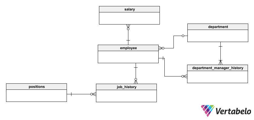
The goal is for employers to manage information about employees and facilitate the storage of this important data. The tables store information about employees, including their job history in the company, salary history, and other important matters.
Now that we have the basic shape of the data model, we can progressively build up the information that is stored in each table. We do this by adding attributes to each entity; these attributes are details that describe each entity. For example, the attributes we use to describe each employee include their first and last name, employee ID number, email address, hire date, and department ID. Each attribute is assigned a general data type, such as string, integer, etc.
We also establish primary and foreign keys to create relationships between entities. For example, the department_id field in the employee table points to the department_id field in the department table. This allows us to link each employee to the department they work in.
In Vertabelo, you can easily and automatically convert the logical model to the physical model. This transforms the entities into tables and assigns DBMS-specific data types to each attribute.
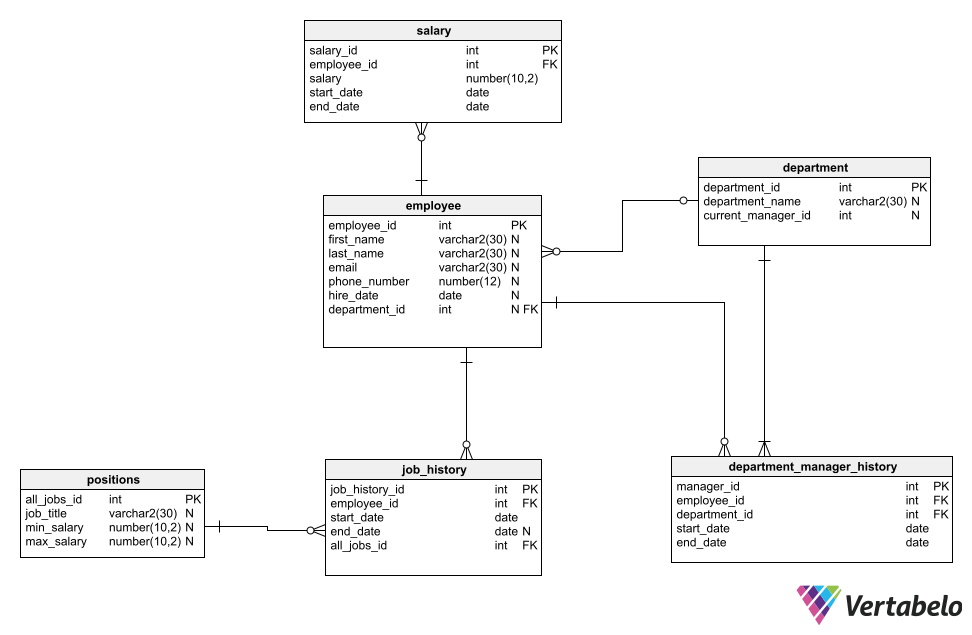
Now we’re in the physical model. You can see the details of the tables and how the tables are linked together:
employee: Each employee has a unique ID. As mentioned, we also store their name, email, phone number, and hire datejob_history: Each employee has a history of roles within the company. These are stored with the employee’s ID, a reference to thepositionstable, and the start and end dates when the employee held this position. We use an artificial ID as the primary key (job_history_id) on this table; the system will need to programmatically check that an employee only has one current job and that the start date of a new job is after the end date of the previous job.positions: This lists all jobs within the company and the salary range for each role. This helps HR manage the different types of jobs. We would need to programmatically ensure that an employee's current salary falls within the range specified for their role.department: This lists the departments within the company and each department’s manager. Employees are assigned to a department via thedepartment_idfield in theemployeeFor now,department_idis not mandatory, but that could be changed to ensure that every employee is assigned to a department.department_manager_history: This table indicates which employee is the manager of a department as well as when they held this position. We keep a history of managers for the department by having an artificial ID as the primary key (manager_id) for this table.salary: This stores the salaries that each employee has had during a specific time (start_datetoend_date). We will again use an artificial ID as the primary key on thesalarytable, so programmatic logic is needed to ensure that an employee has only one current salary for her job (even if having more than one salary would be nice!).
Obviously, we could add more information like employee qualifications, bonuses and commission within the salaries table, holiday/leave plans and history, and eventually information such as users and roles/permissions that an employee has within the system. One way to plan for future adjustments to your model is by adding notes into the model.
From ER Diagram to Employee Database
Let’s fast-forward to creating the database by generating the SQL script. Vertabelo will automatically generate the Data Definition Language (DDL) script for creating the database. Below you can see an excerpt of the DDL code generated for the employees database.
-- Created by Vertabelo (http://vertabelo.com)
-- Last modification date: 2023-10-06 13:58:10.992

-- tables
-- Table: employee
CREATE TABLE MYDB.employee (
    employee_id varchar2(30)  NOT NULL,
    first_name varchar2(30)  NULL,
    last_name varchar2(30)  NULL,
    email varchar2(30)  NULL,
    phone_number number(12)  NULL,
    hire_date date  NULL,
    department_id varchar2(30)  NULL,
    CONSTRAINT CHECK_2 CHECK (( employee_id IS NOT NULL )),
    CONSTRAINT EMPLOYEE_pk PRIMARY KEY (employee_id)
)  NOCACHE
;

-- Table: department
CREATE TABLE MYDB.department (
…
Notes on Building Your Own Employee ER Diagram
Now you can see that creating an ER diagram is a step-by-step process: going from simple to complicated by thinking about your requirements and adding details. Database design for an employee management system may seem like it is overwhelming, but tools can make the task easier by providing hints on potential problems.
