

If you need an ER diagram for an online shopping system, look no further. In this article, you will get a complete database model for online shopping as well as a step-by-step guide to building it. We’ll also talk about some ideas to extend the model.
An ER diagram is a blueprint for creating the foundations of any application that uses information stored in databases. Data modelers use the ER diagrams like architects use their drawing boards: on an empty canvas, they place the elements that make up the structure of what they are going to build. Eventually, that blueprint is ready to become the final product – in the case of the architect, a house or a building; in the case of the data modeler, a database. If you’re not familiar with the work a data modeler does, you can get an idea by reading about the basics of data modeling in 10 minutes.
Any application that uses a database should have in its design documentation an ER diagram that reflects the structure of the stored data. If your application offers standard functionality – such as an online banking or ticket booking application – then its ER diagram need not be created from an empty canvas. There are pre-designed ER diagram templates that solve most of your needs; you can find many in this collection of example ER diagrams.
Online shopping apps also feature fairly standard functionality, so you can find many examples of ER diagrams for online shopping that solve essential needs. In this article, we’ll offer you an ER diagram for online shopping that you can use to incorporate as part of an e-commerce app with standard online shopping functionality. You may want to read some basic information on what an ER diagram is to be prepared for what follows.
What Conditions Must an Online Shopping ER Diagram Meet?
A database model for an online shopping system must be able to store information about the customers who register on the site and place orders. It must also store information about the products available for purchase, indicating price and stock data for each product. Customers must be able to have a shopping cart, where the products they choose from the catalog are stored before the customer is ready to place their order. In turn, each customer should be able to maintain a wish list (i.e. a list of products that they are interested in purchasing) without having yet included them in a shopping cart. When the customer confirms an order, the data model must be able to record the order data as well as payment and shipping information.
As general conditions, the ER diagram for an online shopping system must be normalized up to the third normal form. The reason for this is that the online shopping system is purely transactional, so it must support constant and concurrent updates of the tables that make up the schema. And it must support those updates while strictly maintaining data integrity and consistency.
Next, we will see step by step the construction of an ER diagram for an online shopping system, analyzing at each moment the design decisions that guide its development. You should familiarize yourself with a database designer’s tasks to know how to carry out the project of building an ER diagram for online shopping. The process starts by sketching a conceptual model, then converting it to a logical model, and finally to the physical model. I suggest you read about conceptual, logical, and physical data models for more information on the specifics of each.
Step 1: Building a Conceptual Data Model for Online Shopping
To outline a conceptual database model for an online shopping system, the first thing to do is to identify the entities involved in the system and their attributes. In the vast majority of online shopping data models, the following entities can be found:
Customer: This entity represents the customers who create an account to place orders on the online shopping platform.Product: Represents the set of products available for purchase on the platform.Category: Categories in which the products are grouped.Order: Product orders placed by customers.Order_item: Each item that is part of an order.Payment: The payment made by the customer once the order is completed.Shipment: Shipping information associated with an order, including delivery address and tracking information.Cart: The customer’s virtual basket or shopping cart, which stores items before they are purchased and become part of an order.Wishlist: Stores items chosen by the customer for possible future purchases.
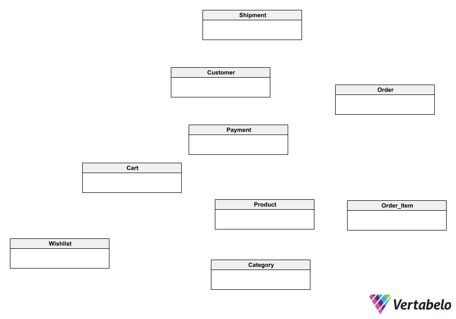
To build our ERD for an online shopping platform in Vertabelo, we can start by drawing the entities without relationships or attributes.
The relationships between the entities are as follows:
- A customer can place several orders. Therefore, between
CustomerandOrderthere must be a one-to-many relationship. - An order can contain one or several items, each of which represents a single product.
Order_Itemis a dependent entity ofOrder, since it has no reason to exist if an order does not exist. In addition,Order_Itemis related toProductthrough a one-to-many relationship: eachOrder_Itemis related to oneProduct, and aProductcan be related to multipleOrder_item - An order is associated with one payment and one shipment, but each payment and each shipment can include multiple orders. For this reason, there are one-to-many relationships between
PaymentandOrderand betweenShipmentandOrder. - A product can belong to a single category: there is a one-to-many relationship between
Productand Category. - The shopping cart and the wish list are dependent entities of
Customer, so bothCartandWishlistmaintain a dependency relationship withCustomer. In turn, each instance of Cart and ofWishlistis related to a product, so both entities have many-to-one relationships withProduct.
Having identified all the entities that make up our model and the relationships between them, we can draw the conceptual model. To do this, we take the ER diagram from above and connect the entities with the corresponding types of relationships as explained before.
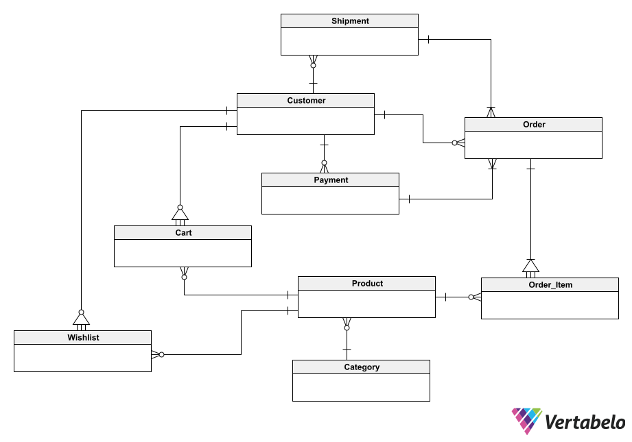
By adding the relationships to our ER diagram, we have a conceptual model that we can use as an outline to discuss with the rest of the software development team.
The conceptual model we have created so far is useful to show to the project stakeholders and get an initial validation from them. For this task, it is useful to use text notes in data modeling.
Step 2: Build the Logical Model
Let’s move forward with our ER diagram for online shopping. After identifying the entities that compose it and sketching the conceptual model, we need to define the attributes that compose each entity. Once we have added the attributes, we will have a complete logical diagram.
It is important to highlight that all the entities must have a primary identifier so that later (in the physical model) all the tables will have a primary key. I suggest you read about what a primary key is if this isn’t already familiar.
For this model, an important decision that determines its design is that each entity has a substitute primary key. The reason for using surrogate keys is that, in transactional systems – such as online shopping systems – the requirements are quite susceptible to change over time. That is why having a surrogate key in all tables can save us headaches in the future. For example, in the Product table, SKU could be a natural key that would make it unnecessary to create a substitute key for the table. But it could happen that another attribute is added to this table – Warehouse, for example – and the same SKU could be repeated for different warehouses. Then the natural key would become SKU + Warehouse, which would put us in a real nightmare for redesigning the database.
In each case, the attribute name that acts as the primary identifier is the table name followed by _id_”) that can be changed at the designer’s discretion. It doesn’t matter which naming convention is chosen. The important thing is that there is one and that it is always maintained.
Let’s see then what the entities with their attributes look like. In the following lists, I detail only the attributes of each entity without their foreign or dependency keys. Both foreign and dependency keys will appear automatically when deriving the physical model.
Also, note that this is a list of the basic attributes of each entity. To build your own ER diagram for online shopping, you can add as many attributes as you consider necessary.
Entity Construction
Let’s start with the Customer entity. We’ll define attributes for the customer’s first and last name, email address, postal address, and phone number.
| Customer | |
|---|---|
| customer_id | integer |
| first_name | string |
| last_name | string |
| string | |
| password | string |
| address | string |
| phone_number | string |
Cart and Wishlist are dependent entities of Customer. Cart includes each product added to the shopping cart and the quantity of the product. It should be noted that I didn’t include the product or any attributes that constitute foreign keys (read this article learn about foreign keys) in this list. This is because these will be added to the model when it is converted into a physical ER diagram.
| Cart | |
|---|---|
| cart_id | integer |
| quantity | integer |
Wishlist simply contains a list of products. Following the same reasoning as above, I didn’t include the product as an attribute; it will appear automatically when we create the physical diagram.
| Wishlist | |
|---|---|
| wishlist_id | integer |
The next entity is Product, with attributes to store SKU, description, price and stock for each product.
| Product | |
|---|---|
| product_id | integer |
| SKU | string |
| description | string |
| price | decimal |
| stock | integer |
The Category entity is very simple; the only attribute it needs (besides the surrogate key) is the category name.
| Category | |
|---|---|
| category_id | integer |
| name | string |
The Order entity stores the date of each order and its total price.
| Order | |
|---|---|
| order_id | integer |
| order_date | date/time |
| total_price | decimal |
Its dependent entity, Order_Item, stores the quantity and price of each item included in an order.
| Order_Item | |
|---|---|
| order_item_id | integer |
| quantity | integer |
| price | decimal |
The Payment entity stores the date of payment, the means of payment, and the amount paid.
| Payment | |
|---|---|
| payment_id | integer |
| payment_date | date |
| payment_method | string |
| amount | decimal |
And finally, Shipment stores the shipping date, address, city, state, country, and postal code.
| Shipment | |
|---|---|
| shipment_id | integer |
| shipment_date | date |
| address | string |
| city | string |
| state | string |
| country | string |
| zip_code | string |
Once we have added the attributes to the entities, the logical model will be complete.
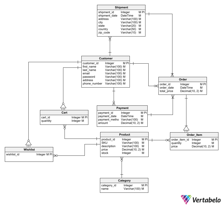
After adding the attributes, the logical model is complete.
Possible Improvements to the Online Shopping ERD
There are several improvements we could make to this scheme, but we’ll leave them aside so as not to make the model too complex. For example, instead of storing the password with the customer data, we could add a user authentication subschema, following the best practices for a user authentication module.
Another possible improvement would be to separate the stock and price data from the product information itself, as this data can vary depending on different factors (e.g. the customer’s geographical location, stock in/out movements, etc.). To give more functionality to the data model, it would be desirable that the stock and price of each product be obtained from other tables. But for the sake of simplicity, we will leave these as product attributes.
Step 3: Create the Physical Model
Once we have the logical model complete and validated by the stakeholders, we are in a position to transform it into a physical model. To do so, we just need to ask Vertabelo to generate the physical model from the logical one. But before doing this, I advise you to read the 8 things to consider when creating a physical data model.
To create the physical model, Vertabelo requires us to choose the relational database management system (RDBMS) on which we will mount our database. To do this, it provides us with a list of options that includes the most popular database engines. The choice of RDBMS will determine some characteristics of the physical model that may vary from one engine to another – e.g. the data type assigned to each attribute.
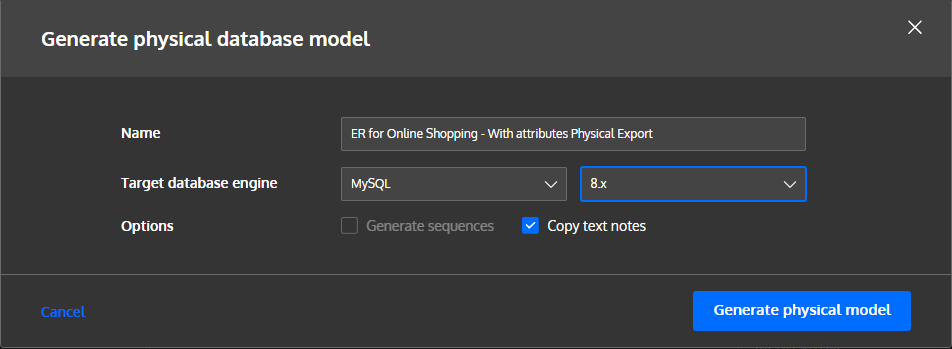
For this example, we chose MySQL 8.x as the target RDBMS. As we can see in the example below, the physical model conversion has added foreign key columns to the correct tables. These are established from the relationships we defined in the logical model.
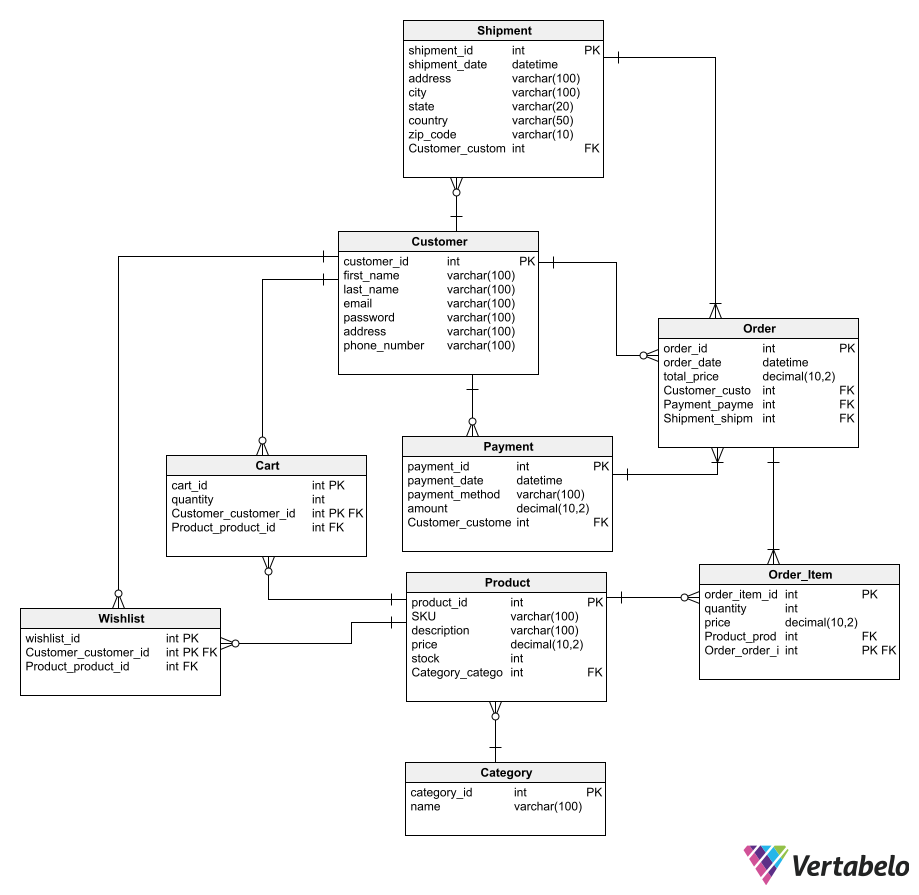
The physical model adds the columns that constitute the foreign keys and the dependency keys.
Let’s examine the Wishlist table as an example. In the logical model, the Wishlist entity only had the attribute wishlist_id, which was used as the primary key. When it becomes a table in the physical model, two more columns appear: Customer_customer_id and Product_product_id. These two columns are foreign keys to the Customer and Product tables, respectively.
Now it only remains to ask Vertabelo to generate the SQL script. We will execute it in the RDBMS and leave the database ready to connect it to the application and start receiving information.
A noteworthy aspect of the generated physical model is that the dependent entities – Cart, Wishlist, and Order_Item – have a primary key composed of two attributes. One of them is a surrogate key (an arbitrary ID) and the other is a foreign key that relates to the primary key of the entity on which it depends. This can be seen more clearly in the automatically generated script. For example, let’s look at the DDL code generated by Vertabelo to create the Cart table:
-- Table: Cart
CREATE TABLE Cart (
	cart_id int NOT NULL,
	quantity int NOT NULL,
	Customer_customer_id int NOT NULL,
	Product_product_id int NOT NULL,
	CONSTRAINT Cart_pk PRIMARY KEY (cart_id,Customer_customer_id)
);

-- Reference: Cart_Customer (table: Cart)
ALTER TABLE Cart ADD CONSTRAINT Cart_Customer FOREIGN KEY Cart_Customer (Customer_customer_id)
REFERENCES Customer (customer_id);

-- Reference: Cart_Product (table: Cart)
ALTER TABLE Cart ADD CONSTRAINT Cart_Product FOREIGN KEY Cart_Product (Product_product_id)
REFERENCES Product (product_id);
We can see that the Customer_customer_id column is both part of the primary key of Cart and a foreign key to the Customer table, relating to the customer_id column of the latter. The Product_product_id column, on the other hand, is only a foreign key to the Product table. This is because Cart is not a dependent entity of Product, as it is of Customer.
Customize Your Own Online Shopping ER Diagram
We’ve seen the necessary steps to create a basic ER diagram for online shopping and convert it into a working database on an RDBMS. As we mentioned earlier, this model can accept many enhancements to provide more robust security or instantly updated price and stock information. Enhancements could also be applied to facilitate the maintenance of the products table – adding new products, modifying the data of existing ones, or discontinuing products – without affecting the registration of orders, payments, and shipments. You can practice adding all these improvements directly by modifying the ER diagram in Vertabelo.
